MIB2 sound settings and datasets are a highly speculated topic: the web is full of comrades who flash “magic” files for money to turn an ukulele into a rock band. Now is a time to shed some light on this.
My personal interest was to bring back the separate subwoofer control that existed for the Audi Sound System in the MIB1 unit but disappeared after the upgrade to MIB2. (Owners of facelifted cars are naturally unaware of such a loss, but retrofitters are offended.) 😕
Connection and Channel Routing
This article is going to cover only audio installations connected to the built-in MIB amplifier. In a rough simplification, these are the three main PR-codes of the car configuration:
8RE — 4 speakers
8RM — 8 speakers
9VD — 9.1 system with central channel and subwoofer
In addition to those, there are in-between configurations with other 8R* codes, but they are pretty rare.
Datasets and features of external amplifiers connected to MOST bus will be another topic to discuss, and I will not touch it here. The majority of these systems have PR-code 9VS.
Electrically, an internal amplifier of the MIB unit has 6 channels and can work in 3 modes: stereo, quadro, and 5.1. All the “extra” speakers and twitters are connected to the main channels through crossovers in pillars or doors.
Location of audio channels on the main 52-pin connector:

Datasets
MIB2 has a dozen addresses where datasets are stored. The full list is compiled here by lprot.
I focused my research on these two:
0x003000: audio_parameter_sound_dataset — all math of sound processing by the DSP is saved here: audio effects, filters, delays, limiters. It is 80% identical to the same MIB1 dataset stored at the 0x001000 address. The description below applies to both.
0x003B00: audio_parameter_sound_configuration_dataset — visual controls: menu items and knobs of user interface.
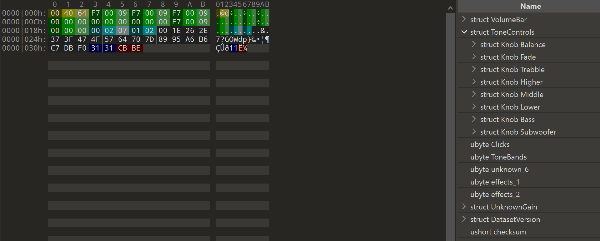
First of all, HEX data from XML files should be extracted and converted to binaries. In this form, they are much easier to analyze. I wrote several scripts to do so; more about them below. As a result of several long nights, I created a coloring template for 010 Editor:
Dataset 0x003B00
Console output:

Volume control is the first 3 bytes: maximum value could be 96, 100, or (in a unique case of Skoda Kodiaq) 115 dB. The second byte (most likely) determines the increments of volume – the bar consists of 30 segments with default value.
Then there are groups of 3 bytes, with the number of steps to each direction for balance/fade and equalizer bands (few cars have ±6 values, but mostly it is ±9). Next, several flags to enable/disable menu items, the number of visible equalizer bands and names of two sound focusing effects.
In the end, there is a scale of 19 increasing values, absolutely identical in all cars. The real purpose is not clear, but I have an assumption – it will be further in the description of the 0x003000 file.
Every 5F dataset ends with two chars of dataset version (displayed in ODIS after flashing) and a checksum, calculated with CRC-16/CCITT algorithm.
The next file was much more interesting. For a better understanding of its contents, it is worth conducting a small educational class:
Sound Processing
To play ready-made tracks, all sound processing comes in an attempt to compensate curvy (faulty) frequency response of your speakers to a perfect zero. This process can be illustrated as follows:
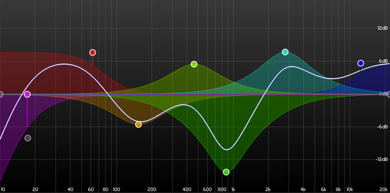
Sound composers add special points (filters) to the frequency graph that change the curve by their presence. You may think about them as black holes distorting the space/time of the universe. Very simple math describes the filters, and (in a very minimal case) they consist only of X and Y coordinates. There are several types of points:
Peak point (same as Notch, Bell) makes a hill or a dip at some frequency with specified force (gain) applied at some range (radius / resonance / quality). (Various software use several terms, I used “quality” in my parser. I’m sure experts will correct me in the comments.) An example above has 4 peak points: yellow 🟡, light green 🟡, green 🟢, and turquoise 🟢.
Lowpass / Highpass filters (purple 🟣 point) assume only one further direction of the graph and drag it down to the end from the left (low) or right (high) sides.
Low Shelf / High Shelf filters (red 🔴 and blue 🔵 points) cause the graph to go down or up by a certain level (gain) within their range but don’t affect it further.
Much better (and more correct) filter effects are described in these articles:
- What are the Different Types of EQ and Filters?
- EQ Shelving : High Shelf And Low Shelf Filters Explained
- EQ: The Ultimate ‘How-to Guide’
And now, get back to the practice:
Dataset 0x003000

There are stored:
Amplifier signal mode (2, 4, 6 channels)
5 filters used by tone equalizer (3 prefilled in VW/Skoda/Seat cars, Audi has only 2)
Subwoofer gain range
2 filters with 19-byte scales to raise the level of high and low frequencies at low volume. This effect completely disappears only at the 19th step, which is further than the middle of the volume bar.
Table of 7 GALA levels, 19 values per row – this is the speed-dependent volume control. Presumably, a scale from the 0x003B00 dataset is used here as column headers. The values are very similar and finish at 240 (km/h?).
2 unknown filters with their dependency scales, 19 values each. The first filter has zero gain for most cars. It looks like the second one (or both) describes the math of GADK (technology paired with GALA – speed-dependent dynamic range compression).

After the global DSP processor settings, there comes two profiles of personal filters for each of the 6 audio channels. Their order is the same as on the MIB connector: 1 – right rear, 2 – right front, 3 – left front, 4 – left rear, 5 – subwoofer, and 6 – center channel.
Each channel has its own volume level, delay, phase, and 7 filters to correct the frequency response of a speaker: the first 3 filters have 16-byte tails, but I did not find a single one that uses them.
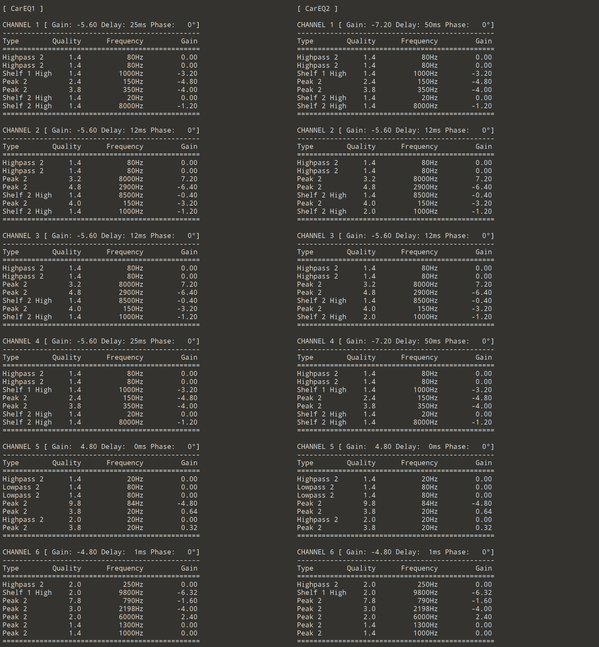
Then there are 7 unknown bytes (3 purple ones sometimes aren’t null), and per-channel Dynamic Range Compression spreadsheet.

DRC lowers the signal after reaching the Threshold value of -2dB (lower the value – earlier the point to cut it; maximum value with no DRC effect is 0) during the Attack time (10ms), and keeps on this level for the Hold time (0ms), then returns back to initial signal during the Release time (200ms).
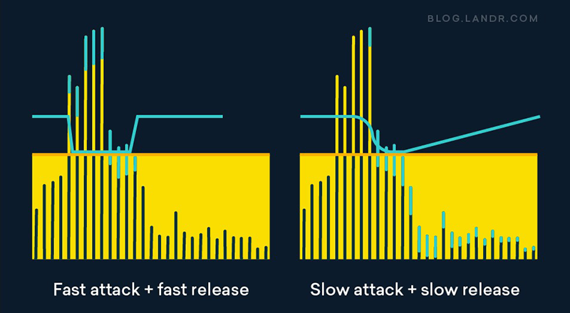
Several articles with the right description of math applied:
- Music 101: What Is Dynamic Range Compression?
- How to Use a Compressor for a Better Mix
- Dynamic range compression (wiki)
Many Seat models have these values set to their minimums of [0, 0.5, 0.5], which, in theory, should produce a more detailed and crisp sound. The main question – is it just laziness of the engineers, or do they trust factory speakers so much?
Applying Theory to the Real World
I personally don’t believe that changing frequency curves and delays without special measuring equipment can improve sound quality, nor uploading datasets of cars with 1.5 times larger or smaller saloons than yours.
But nulling all channel effects can really help professional acoustic installers when replacing speakers or connecting the MIB to an external amplifier for raw output.
The apparent usage of modified datasets is the activation of disabled control knobs and the second sound profile. You can try to write something interesting from other cars into it. Edits of the 0x003B00 dataset are also limited by items available in the MIB2 user interface -– all Audi’s equalizers have only two bands (and they even kept that in MIB3).
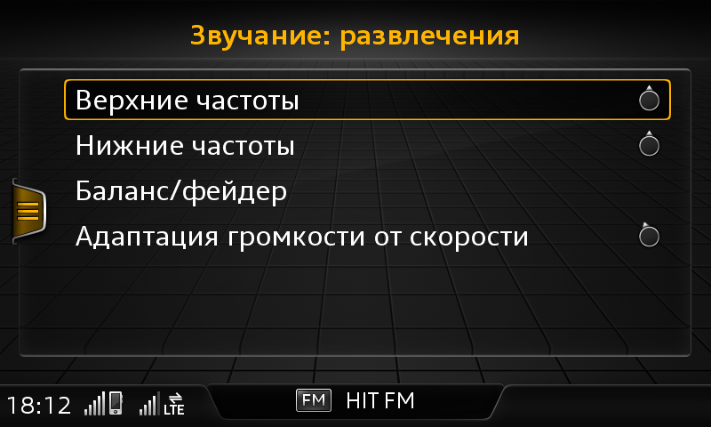

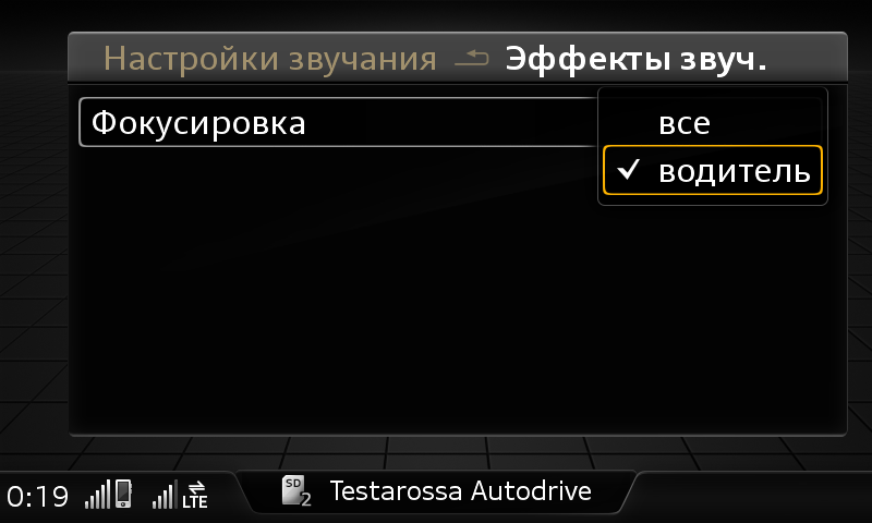
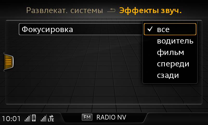
The 31st and 32nd bytes of the 0x003B00 dataset control the names of two profiles available in the “Sound Focusing” drop-down: 00 – hidden, 01 – All, 02 – Driver, 04 – Movie, 08 – Front, 16 – Rear.
Setting both bytes to FF oddly enables the list of 6 options, but selecting any of them does nothing – only two profiles are stored in the 0x003000 dataset.
Conclusions
Three coloring templates published to GitHub:
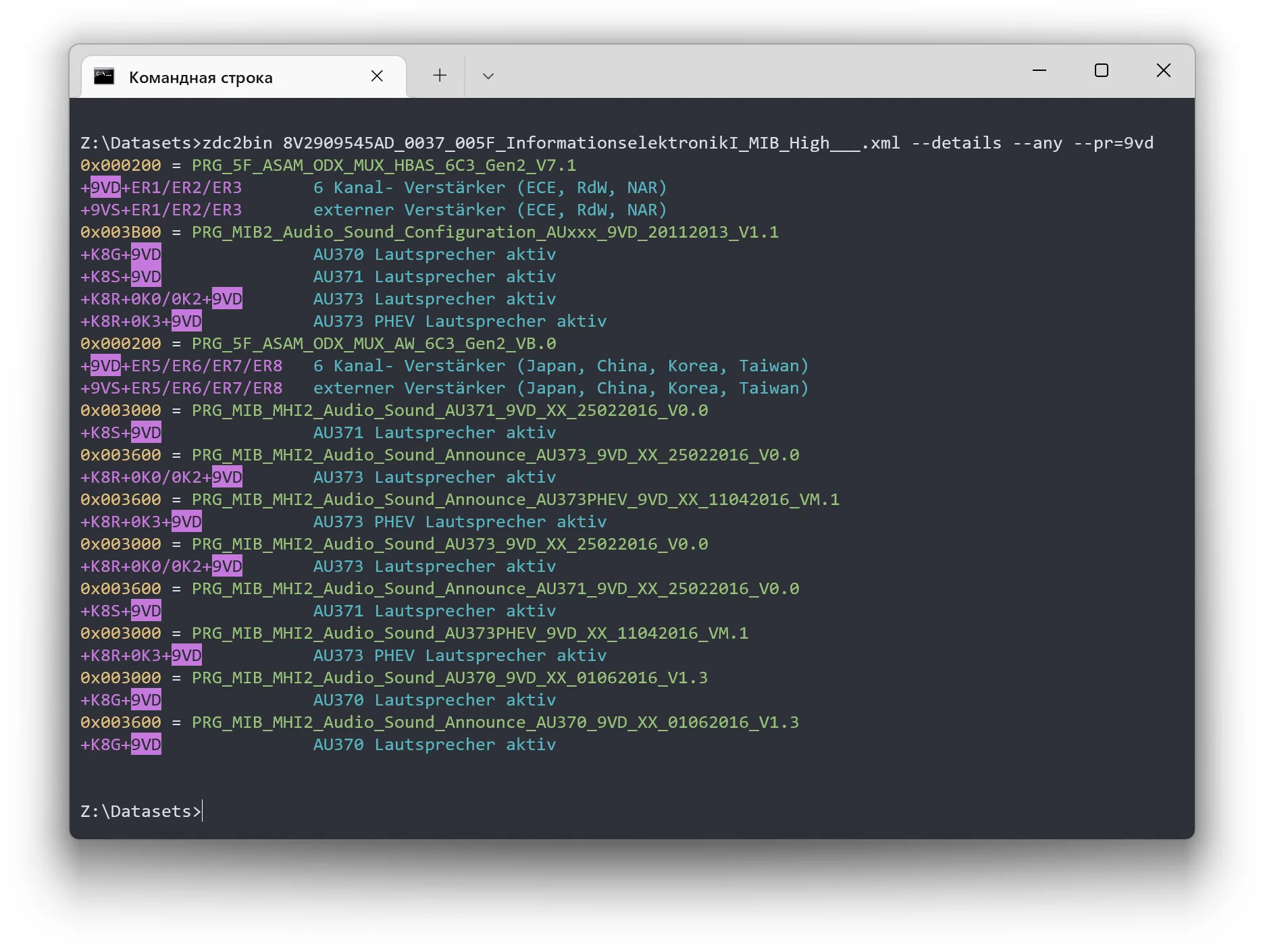
There are 3 command-line tools in the tools/bin folder: to extract .bin from ZDC-containers and single XML-files of ODIS and to create new XMLs out of binaries with automatic checksum calculation. Screenshot examples:

I also did a quick look at MIB3 datasets, and they look very similar: 0x007204 is identical to MIB2’s 0x003B00, with UI controls, and 0x007201 — the same as 0x003000, with per-channel DSP filters.
Stay tuned…

Comments
temp temp